您好,欢迎光临 湖南中森通信科技有限公司

1 产品概述
抗干扰卫星导航天线是一种专门设计用于在复杂电磁环境中保持卫星信号稳定接收的高性能天线,主要应用于地面平台、航空、航海及关键基础设施等领域,以确保卫星导航信号在干扰条件下的可靠性,抗干扰卫星导航天线的性能直接决定了复杂电磁环境下的定位可靠性,随着抗干扰技术的提升,抗干扰天线将向着智能化、集成化和多模融合方向发展。
100mm×100mm 四阵元抗干扰天线(以下简称“抗干扰天线”)支持BDS B1 、GPS L1 、Galileo E1(可扩展支持 GLONASS G1)频点信号的接收、放大、下变频、滤波、抗干扰处理和上变频输出,采用+9V~+32V 电压供电,可实现抗1~3 个来向宽带、扫频和脉冲等多种压制干扰及抗上述干扰组合能力。
该抗干扰天线外形尺寸小、功耗低、具有两个外部接口,可内置接收机,支持 PVT 解算输出,是抗干扰用户端应用的理想解决方案。
抗干扰天线由抗干扰天线、调测试线缆及随机文件组成,组成明细如下:
表 1 产品齐套性(单套产品)
|
序号 |
产品名称 |
数量 |
备注 |
|
1 |
抗干扰天线 |
1 个 |
100mm×100mm |
|
2 |
调试线缆 |
-- |
J30J调试转接,选配 |
|
3 |
安装螺丝 |
1 组 |
1组 5~6 颗安装螺丝 |
|
产品规格 |
说明 |
是否支持 |
|
系统模式 |
BD |
支持 |
|
GPS |
支持 |
|
|
GLONASS |
可支持 |
|
|
Galileo |
支持 |
|
|
信号类型 |
BDS_B1C/B1I/B1A |
支持 |
|
GPS_L1C/A |
支持 |
|
|
GLONASS_G1 |
可支持 |
|
|
Galileo_E1 |
支持 |
|
|
抗干扰类型 |
B1 、L1 、E1(扩展支持 G1)宽带、窄带、扫频、脉冲及组合干扰 |
支持 |
|
抗干扰强度 |
单宽带:干信比≥110dB@-130dBm |
支持 |
|
三宽带:干信比≥95dB@-130dBm |
支持 |
|
|
抗干扰空域范围 |
方位0°~360°, 俯仰-90°~90° |
支持 |
|
射频输出 |
射频输出功率:-60dBm~-70dBm |
支持 |
|
射频阻抗:50 欧姆 |
支持 |
|
|
输出驻波:≤2.0 |
支持 |
|
|
内置接收机定位测速精度 |
定位精度:水平≤7m,高程≤9m; 测速精度:≤0.2m/s |
支持 |
|
抗烧毁能力 |
≥10W |
支持 |
|
工作电压范围 |
9V~32VDC |
支持 |
|
正常工作功耗 |
≤11W |
支持 |
2 产品规格
1、支持 BDS_B1、GPS L1、Galileo E1(扩展支持 GLONASS G1)频点信号的接收。
接收频段范围如下:
B1C:1575.42MHz±2.046MHz;
B1I:1561.098MHz±2.046MHz;
B1A:1575.42MHz±16.368MHz;
L1C/A:1575.42±1.032MHz;
L1C:1575.42±7.166MHz;
E1 :1575.42±2.046MHz;
G1 :1598.0625-0.5~ 1605.375+0.5MHz。
2、具有 B1 、L1 、E1(可扩展支持G1)频段内抗宽带、扫频和脉冲等多种压制干扰及抗上述干扰组合能力。
3、射频通道支持硬直通和抗干扰模式输出,可通过串口选择输出模式。
4、天线内置接收机,支持抗干扰天线模式和接收机工作模式,其中默认工作在抗干扰天线模式,通过射频接口输出经过抗干扰处理后的射频信号;当切换到接收机模式下,则采用内置接收机进行抗干扰后定位解算和结果输出。
1、频点抗干扰能力:
(1) 阵元数量:4 个;
(2) 抗干扰类型:支持抗 B1、L1、E1(可扩展支持G1)频段的宽带、扫频和脉冲等多种压制干扰能力,及抗上述干扰组合的能力;
(3) 抗多干扰个数:同时对抗 1~3个不同方向干扰源;
(4) 抗单宽带干扰能力:干信比≥110dB@-130dBm;
(5) 抗三宽带干扰能力:干信比≥95dB@-130dBm;
(6) 抗干扰空域范围:方位0 °~360 °, 俯仰-90 °~90°。
注:俯仰角定义为抗干扰源与抗干扰天线空间矢量与水平的夹角,以机体系y轴为俯仰轴,逆时针方向为“+”,顺时针方向为“-”。
2、射频输出:
(1) 射频输出功率:-60dBm~-70dBm;
(2) 射频阻抗:50 欧姆;
(3) 输出驻波:≤2.0。
3、内置接收机(可扩展支持)指标:
内置接收机支持完成 B1、L1、E1(可扩展支持G1)频点信号接收解算,并通过数据接口输出定位结果:
(1) 定位精度:水平误差≤7m(水平),高程误差≤9m。(95%,PDOP ≤4);
(2) 测速精度:≤0.2m/s(95%)。
4、天线口面抗烧毁能力:≥10W。
5、工作电压范围:9V~32VDC。
6、正常工作功耗:≤11W。
1、尺寸:长宽 100.0mm × 100.0mm(公差≤±0.5mm),高≤23mm(误差≤±0.5mm)。
2、天线颜色:银灰色,74 B04(GSB05-1426-2001)。
3、天线重量:≤300g(不含调试线缆)。
4、安装接口: 天线底部和侧面,各有四个安装螺孔,底部规格为 4 个 M3 螺孔深度 5.5mm,侧面为 4 个M2.5 螺孔,深度 3mm,安装脚 4 个 M3 螺丝。
5、外观质量:产品外表应清洁、完整,无破损、变形、锈蚀、霉斑、污迹、镀涂层脱落及明显划痕、毛刺;接口连接器与控制元件应完整、装配牢固,无污浊、变形、锈蚀等机械损伤;紧固件应装配到位、牢固可靠。
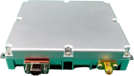
天线具备两个外部接口:1 个 J30J 电源数据接口、1 个 SMA-K 射频输出接口,用于天线放大及抗干扰处理后的 B1、L1、E1(可扩展支持G1)频点信号输出。
1、平均故障间隔时间MTBF:≥2000h;
2、连续工作时间:≥24h。
1、工作温度:-40℃~+70℃, 10%~90%RH(无结露);
2、贮存环境:-45℃~+85℃, 10%~95%RH(无结露);
3、防水等级:不低于 IP65。
Anti-jamming satellite navigation antenna is a high-performance antenna specially designed to maintain stable reception of satellite signals in complex electromagnetic environments. It is mainly used in Land-Based Platform , aviation, maritime, and critical infrastructure fields to ensure the reliability of satellite navigation signals under jamming conditions. The performance of anti-jamming satellite navigation antennas directly determines the positioning reliability in complex electromagnetic environments. With the improvement of anti-jamming technology, anti-jamming antennas will develop towards intelligence, integration, and multi-mode fusion.
100mm×100mm four-element anti-jamming antenna (hereinafter referred to as "anti-jamming antenna") supports the reception, amplification, down-conversion, filtering, anti-jamming processing, and up-conversion output of BDS B1, GPS L1, Galileo E1(Extended Support for GLONASS G1) frequency signals. It is powered by +9V~+32V voltage and can resist 1~3 sources of broadband, frequency-sweeping, pulse, and other suppression jamming as well as combinations ofthe above jamming.
This anti-jamming antenna features small size, low power consumption, two external interfaces, and support for built-in receiver and PVT solution output, making it an ideal solution for anti-jamming user-end applications.
The anti-jamming antenna consists of an anti-jamming antenna, debugging cables, and random documents. The detailed composition is as follows:
Table 1 Product Completeness (Single Set Product)
|
Serial Number |
Product Name |
Quantity |
Remarks |
|
1 |
Anti-Jamming Antenna |
1 |
100mm×100mm |
|
2 |
Debugging Cable |
-- |
J30J debug adapter, optional |
|
3 |
Fixing Screw |
1 set |
1 set (5-6 screws) |
Figure 1 Product Front View (Reference)
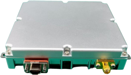
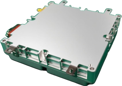
Figure 2 Product Back View (Reference)

|
Product Specification |
Description |
Supported |
|
System Mode |
BDS |
Yes |
|
GPS |
Yes |
|
|
GLONASS |
Extended Support |
|
|
Galileo |
Yes |
|
|
Signal Type |
BDS_B1C/B1I/B1A |
Yes |
|
GPS_L1C/A |
Yes |
|
|
GLONASS_G1 |
Extended Support |
|
|
Galileo_E1 |
Yes |
|
|
Anti-jamming Type |
B1, L1, E1(Extended Support for G1) broadband, narrowband, frequency- sweeping,pulse,and combined jamming |
Yes |
|
Anti-jamming Strength |
Single broadband: Jamming-to-signal ratio ≥110dB@-130dBm |
Yes |
|
Three broadbands: Jamming-to-signal ratio ≥95dB@-130dBm |
Yes |
|
|
Anti-jamming Airspace Range |
Azimuth 0°~360°, Elevation -90°~90° |
Yes |
|
RF Output |
RF output power: -60dBm~-70dBm |
Yes |
|
RF impedance: 50 ohms |
Yes |
|
|
Output VSWR: ≤2.0 |
Yes |
|
|
Built-in Receiver Positioning and Velocity Measurement Accuracy |
Positioning accuracy: Horizontal ≤7m, Vertical ≤9m; Velocity measurement accuracy: ≤0.2m/s |
Yes |
|
Anti-burning Capability |
≥10W |
Yes |
|
Operating Voltage Range |
9V~32VDC |
Yes |
|
Normal OperatingPower Consumption |
≤11W |
Yes |
2 Product Specifications
2.1 Main Functions
1 、Supports the reception of BDS_B1, GPS L1, Galileo E1(Extended Support for GLONASS G1)frequency signals.
Reception frequency band ranges are as follows:
B1C: 1575.42MHz±2.046MHz;
B1I: 1561.098MHz±2.046MHz;
B1A: 1575.42MHz±16.368MHz;
L1C/A: 1575.42±1.032MHz;
L1C: 1575.42±7.166MHz;
E1: 1575.42±2.046MHz;
G1: 1598.0625-0.5~1605.375+0.5MHz.
2 、Has the capability to resist broadband, frequency-sweeping, pulse, and other suppression jamming as well as combinations of the above jamming in B1, L1, E1, (Extended Support for G1)frequency bands.
3 、The RF channel supports hard through and anti-jamming mode output, and the output mode can be selected through the serial port.
4 、The antenna has a built-in receiver and supports anti-jamming antenna mode and receiver working mode. The default working mode is anti-jamming antenna mode, which outputs RF signals after anti-jamming processing through the RF interface; when switched to receiver mode, the built-in receiver is used for anti-jamming, positioning solution, and result output.
1 、Frequency Anti-jamming Capability:
(1) Number of elements: 4;
(2) Anti-jamming type: Supports resistance to broadband, frequency-sweeping, pulse, and other suppression jamming in B1、L1、E1(Extended Support for G1) frequency bands, as well as combinations ofthe above jamming;
(3) Number of anti-multi-jamming: Resists 1~3 jamming sources from different directions simultaneously;
(4) Anti-single broadband jamming capability: Jamming-to-signal ratio ≥ 110dB@-130dBm;
(5) Anti-three broadband jamming capability: Jamming-to-signal ratio ≥ 95dB@-130dBm;
(6) Anti-jamming airspace range: Azimuth 0 °~360 °, Elevation -90 °~90 °.
Note: The elevation angle is defined as the angle between the spatial vector of the anti-jamming source and the anti-jamming antenna and the horizontal plane. The body system y-axis is the elevation axis, with the counterclockwise direction as "+", and the clockwise direction as "-".
2 、RF Output:
(1) RF output power: -60dBm~-70dBm;
(2) RF impedance: 50 ohms;
(3) Output VSWR: ≤2.0.
3 、Built-in Receiver Indicators:
The built-in receiver supports receiving and solving B1, L1, E1(Extended Support for G1)frequency signals, and outputs positioning results through the data interface:
(1) Positioning accuracy: Horizontal error ≤7m, Vertical error ≤9m. (95%, PDOP≤4);
(2) Velocity measurement accuracy: ≤0.2m/s (95%).
4 、Antenna Aperture Anti-burning Capability: ≥10W.
5 、Operating Voltage Range: 9V~32VDC.
6 、Normal Operating Power Consumption: ≤11W.
Dimensions: Length × Width 100.0mm × 100.0mm (tolerance ≤±0.5mm), Height ≤23mm (error ≤±0.5mm).
Antenna color: Silver gray, 74 B04 (GSB05-1426-2001).
Antenna weight: ≤300g (excluding debugging cables).
Mounting interface: There are four mounting screw holes on the bottom and side of the antenna. The bottom specification is 4 M3 screw holes with a depth of 5.5mm, and the side is 4 M2.5 screw holes with a depth of 3mm. The mounting feet use 4 M3 screws.
Appearance quality: The product surface shall be clean and intact, without damage, deformation, rust, mildew, stains, coating peeling, obvious scratches, or burrs; the interface connectors and control components shall be complete and firmly assembled, without mechanical damage such as contamination, deformation, or rust; the fasteners shall be properly and firmly assembled.
The antenna is equipped with two external interfaces: 1 J30J power data interface and 1 SMA-K RF output interface, which are used for the output of B1 、L1、E1 (Extended Support for G1)frequency signals after antenna amplification and anti- jamming processing.
Mean Time Between Failures (MTBF): ≥2000h;
Continuous working time: ≥24h.
2.6 Environmental Adaptability
Operating temperature: -40℃~+70℃, 10%~90%RH (no condensation);
Storage environment: -45℃~+85℃, 10%~95%RH (no condensation);
Waterproof grade: Not lower than IP65.


Copyright © 2018 湖南中森通信科技有限公司电话:400-081-5505传真:0731-85244648全国统一服务热线:400 081 5505备案号:湘ICP备18021345号-1 营业执照查询 技术支持:竞网智赢